Soil-Tool interaction
12
12
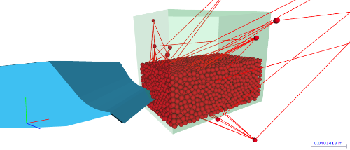
 Ripper.inp Hi all, I am trying to get my head around Granoo but get a bit stuck on the topic of bonds between elements. I am looking to simulate interaction between soil particles and a tool. The attached .inp file works in so far that the tool interacts with the particles, but the particles fly off in all directions. I have made up the domain with the cooker utility. It looks like the particles are paired, but the bond definition is either lacking or not correctly defined ? The Granoo documentation is a bit sparse, if someone could point me in the right direction then that would be greatly appreciated ! Cheers, Peter |
|
Administrator
|
Hello, sorry for the late reply.
Yes, you need to affect mechanical bond to "element pair". If you want beams, you can use the "CONVERT-ELEMENT-PAIR-TO-BEAM" Plugin. You can take a look into the 00010 example. Cheers, Damien. |
|
Hi Damien,
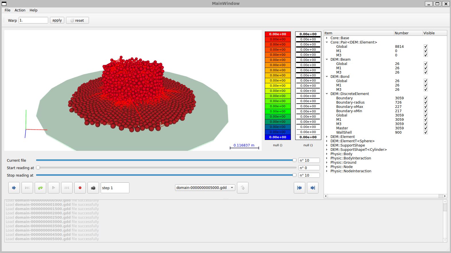
Thank you for your reply. I am still learning and I thought it better to set up an Angle of Repose test to see how various parameters affect the simulation. To that end I have made up the attached .inp file, in which the particles made with cooker settle under gravity and then the support shape cylinder is deleted, so the particles can form a cone. However, the "CONVERT-ELEMENT-PAIR-TO-BEAM" Plugin only makes 26 bonds and there are well over 3000 element pairs untouched. The documentation says the plugin should convert all element pairs ? With only 26 bonds the particles probably will not "clump" together like soil particles would ? Cheers, Peter  Angle_of_Repose_Bonds.inpCookingBook.inp Angle_of_Repose_Bonds.inpCookingBook.inp
|
|
Administrator
|
Hum, probably, the beams reach directlty their ultimate bond strength. Please try :
<CONVERT-ELEMENT-PAIR-TO-BEAM MacroYoungModulus="5e4" MacroPoissonRatio="0.3"/> PS : When a beam is broken, it is directly converted to a "Core::Pair<DEM::Element>" Cheers, Damien |
|
Hi Damien,
Thank you, yes, increasing the bond strength keeps more bonds intact. Here's another question : I have a container with particles (build with CookingBook.inp) which settle under gravity (AoR_Settle.inp), similar to the Bluewave example. Then I import the resulting final .gdd file in AoR.inp for further simulations. But the imported .gdd file doesn't look anywhere like the final imported .gdd file. Do you know what happens there ? It has me confused, am I missing something ? Cheers, Peter CookingBook.inp AoR_Settle.inp AoR.inp |
|
Hi all,
Here's another approach : If importing a "settled" domain doesn't work, then maybe adding a "processing" step works. So the "settling" step is followed by a step in which the cylinder support shape is removed, in order to slump the particles. But at reaching line 50 "<DELETE What="DEM::SupportShape" ID="Container" />" I get an error "Can't find the required item to delete with ID 'Container'. This is strange, the documentation clearly states: [PlugIn] : DELETE id : DELETE source file : Lib/GranOO3/PlugIn/Delete.cpp This plugin delete the specified items. Info Process on : All Multithreaded : No Recommended section: PreProcessing, Processing Required param What (string) The type of item to delete : Core::Base, DEM::Element, Physic::Body, Physic::Ground and so on… Optional param Set (string, default=“Global”) The plugin removes only the particular items that belong to the specified set ID (string, default="") If ID is set, the plugin removes only item with the specified ID. It works only for classes that own ID such as Physic::Ground, DEM::Tool or DEM::SupportShape Example <DELETE What="Physic::Ground"/> <DELETE What="DEM::SupportShape" ID="Boundary"/> AND : [PlugIn] : NEW-SUPPORT-SHAPE id : NEW-SUPPORT-SHAPE source file : Lib/GranOO3/PlugIn/NewSupportShape.cpp Creates a new DEM::SupportShape with a given ID. A DEM::SupportShape is a shape that contains a discrete domain. You can associate the DEM::SupportShape with this discrete domain. If you call UPDATE-SUPPORT-SHAPE PlugIn the length of the support shape is recomputed from the state of its associated discrete elements. Info Recommended section: PreProcessing Required param Type (string) Set the type of the DEM::SupportShape. It must be a Cylinder, a Cone, etc… Optional param ID (string) The ID of the new Ground. The new Ground can be retrieved in C++ code with Physic::Ground::glob("ID") or by its child class such as Physic::GroundT<Shape::Sphere>::glob("ID"). Set (string, default="") put the created tool in the specified set. If the set does not exist, a new one is created. To get the list of all the available attributes please refer to the specific documentation of each tool. To get this documentation, simply run granoo with the following argument granoo -d -f SupportShape Example <NEW-SUPPORT-SHAPE Type="Sphere" Radius="1.0" ID="SHShape"/> If I change in line 15 the ID="Container" to Set="Container", then this error pops up : An error occured while reading the <NEW-SUPPORT-SHAPE> element with raw text : '<NEW-SUPPORT-SHAPE Type="Cylinder" Radius="0.078" Length="0.16" FrameID="F2" Set="Container" />' Cannot find the required attribute 'ID' What to make of it ? Cheers, Peter |
|
Administrator
|
It seems you have a lot of questions! Please send me an email at damien[dot]andre[at]unilim[dot]fr, and we can schedule a short video call so you can ask me everything directly. That will be more efficient.
Cheers, Damien |
|
Hi Damien,
It's all good, I have ironed out all the kinks and getting good results with soil simulations. The attached .inp file generates a soil heap close to what I observed in real, with parameters taken from several research papers for reference. Works out quite well ! AoR_-_2.gif learn.inp |
|
Administrator
|
Sounds great ! You just forget the '°' symbol for the "RollingLimit" option. It should be :
...
<MANAGE-COLLISION Between="Body/Ground ... RollingLimit="20°" ... />
<MANAGE-COLLISION Between="Body/Body"  ... RollingLimit="30°" ... />
...
Cheers, Damien |
|
Thanks Damien,
I will add the"°" symbol and see what effect it has on the simulation. To further my understanding of the collision model : how is the AdhesionForce implemented in the collision model ? I assume it is a force between 2 discrete elements, representing for example Van der Waals forces or an adhesion force similar to 2 soil particles with a water film. The adhesion force is then likely to be very small ? Sorry for asking so many questions, it is a bit difficult to decipher all the possible components for the collision callbacks. Most of the (soil) research literature I have consulted refer to several different models, mainly Hertz-Mindlin model, Hertz-Mindlin with JKR model, hysteric spring model and a EEPA model. It's quite difficult to work out which component from the callbacks relate to a particular model. the Granoo documentation is a bit sketchy on that. Mind you, I do think Granoo is an amazing piece of work ! Cheers, Peter |
|
Administrator
|
This is simply the intensity of the cohesive force (in Newtons) between grains. The direction of the adhesive force is always normal to the contact surface. It can model various cohesive forces, such as capillary forces. The intensity of the force is up to you to define. Cheers, Damien |
|
Thanks Damien,
It's been a bit of a steep learning curve, but have to say Granoo is a very handy bit of software. Simulates soil-tool interaction quite well. One question : is it possible to record the force on the tool ? I know sensors can be used, but I cannot seem to locate the source for the force of a tool. HollowTyneTwin_-_2.gif |
|
Administrator
|
Yes, for sure! You can take a look at example 00034 (the Brazilian test). There, you will see how to capture the force applied to the two plates that compress the sample. Cheers, Damien |
|
Thank you Damien,
I will have a go at that ! Is there a way to assign different colours to elements in a domain, for instance the bottom half of the domain in one colour and the top half in another colour ? That could show the extend of mixing of particles. Or is that a job for ParaView, or use 2 separate domains, a bottom and top domain ? Cheers, Peter |
|
Administrator
|
To assign different colors, you should create a new pre-processing plugin that :
- create one Core::SetOf<DEM::Element> per color - add elements to these SetOf Now, these setof will be always recorded. You can then affect colors with the granoo-viewer (you should right-click the right setof into the treeview) |
|
This post was updated on .
Hi Damien,
Thank you. I figured for the purpose of my simulations I try to use 2 domains, similar to example "BOUNCING-BALL-v0". That way I can use slightly different properties to represent 2 layers of soil and give them different colours in granoo-viewer. The .inp program works fine loading the domains when I leave the "CONVERT-ELEMENT-PAIR-TO-BEAM" and most of the processing out and the domains show in granoo-viewer. However I ran into a problem when I uncomment "CONVERT-ELEMENT-PAIR-TO-BEAM": the cooker shows that the domains have a coordination number of 6.19 and 6.2. But when the Plough.inp program gets to the "CONVERT-ELEMENT-PAIR-TO-BEAM" it throws an error saying "The value of coordination number Cn=0.686328 seems to be false. It is not in the common range of [5, 15]." I have tried both "CONVERT-ELEMENT-PAIR-TO-BEAM" line for each domain, also alternately, but to no avail. In other .inp programs with 1 domain the "CONVERT-ELEMENT-PAIR-TO-BEAM" works without a hitch. What am I missing ? Cheers, Peter Amendment : I used the microscopic parameters from another simulation for the YoungModulus and RadiusRatio when using "CONVERT-ELEMENT-PAIR-TO-BEAM" and that works. I assume something is throwing off the automatic calibration when using 2 domains. That's a pity, because the macroscopic parameters are very handy ! 1000007029.jpg 1000007031.jpg Coord-Number.JPG Plough.inp TopSoil7500.gdd SubSoil4000.gdd |
|
Administrator
|
In such a case, you can force the value of the coordination number (that affects the micro properties of your beam) by using
<CONVERT-ELEMENT-PAIR-TO-BEAM MacroYoungModulus="2e7" MacroPoissonRatio="0.3" MaxRelativeElongation="0.1%" CoordNumber="6.2" Set="M1"/> I am sorry this is not documented. |
|
Hi Damien,
That works a treat, thank you. I have 2 domains with slightly different properties bonds to represent different soil layers. Is it possible to establish element pairs between the elements of the 2 domains and then convert these pairs to bonds ? There is the plugin "BUILD-NEIGHBOUR-ELEMENT-PAIR", but that only works for elements inside a domain ? Or can it also build element pairs between 2 sets of elements ? Cheers, Peter TwoDomains.jpg |
|
Administrator
|
The "BUILD-NEIGHBOUR-ELEMENT-PAIR" is designed to work on a single setof. I think that, in your case, you should writhe your own plugin that detect contact between your yellow and your red setof and then build en alement pair between the two discrete elements in contact. Kind regards, Damien |
|
Hi Damien,
Thank you, I have added a plugin to build element pairs between discrete elements in 2 sets. Cheers, Peter. BuildInterDomainElementPair.cpp BuildInterDomainElementPair.hpp |
«
Return to GranOO
|
1 view|%1 views
| Free forum by Nabble | Edit this page |

